VOCAL’s Multiple Linear Point Constraint Design allows users of a beamforming system to explicitly specify the response of the beamformer for different angles and different frequencies. Our Multiple Linear Point Constraint Design allows full flexibility in designing an exact array response over any angle and frequency. You can construct any array response you desire exactly using our design. Contact us today to discuss your beamforming application requirements.
Multiple Linear Point Constraint Design
We discuss how to extend a Narrow Minimum Variance Distortionless Response (MVDR) beamformer all the way to a Broadband Multiple Linear Point Constraint Design. To extend the constraint system in such a way, we first examine the manifold vector for a narrowband linear array with M microphones, receiving a plane wave with frequency ѡ from angle Ɵ:
When we are dealing with multiple frequencies, we first need to extend the manifold vector by allowing for more taps. To do so, we have:
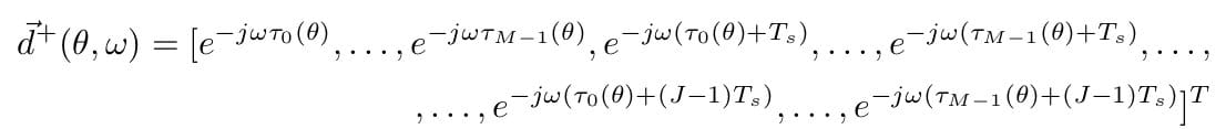 (2)
(2)
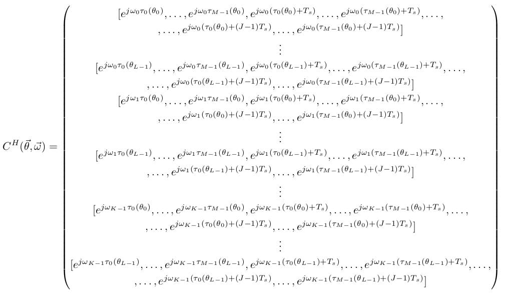
Notice that this still gives us the constraint matrix for a single frequency and angle, except now we are doing broadband processing. To extend to multiple angles, we simply stack constraints on top of one another, and use C to denote the constraint matrix:

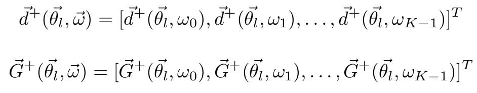
Similarly, we can extend our response vector to accommodate the constraint matrix:
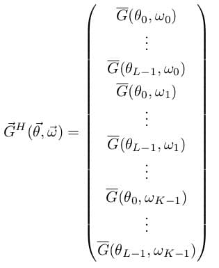
(3)
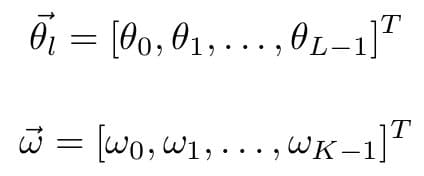
Where L and K are the number of look directions and discrete frequency points respectively. We can of course, make this more compact. To do so, we denote:
 (4) (5)
We can then define:
![]()
![]() (6)
(6)
![]()
![]() (7)
(7)
And so we have:
 (8) (9)
So that we arrive at our Multiple Point Linear Constraint Equation, given by:
![]()
![]() (10)
(10)
Lets say we wish to pass all signals with angles Ɵ→P = [ƟP0, ƟP1, …, ƟP-1], and frequencies ѡ→r = [ѡr0, ѡr1, …, ѡr-1], while nulling out all signals with angles Ɵ→q = [Ɵq0, Ɵq1, …, Ɵq-1], and frequencies Ɵ→t = [Ɵt0, Ɵt1, …, Ɵt-1]. In this case, we need not consider every angle or every frequency possible, instead, we include only the ones we are interested in specifying the response to. We can simply write:
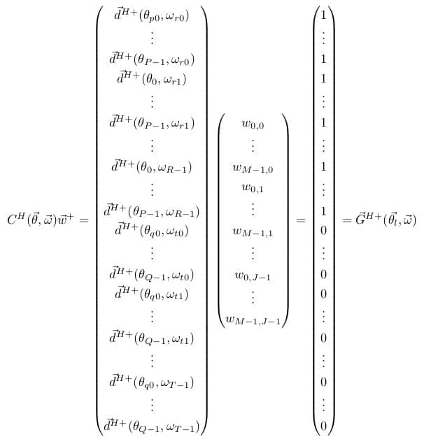 (11)
(11)
Indeed, if there is a set ƟP, ΩP to pass and a set to block ƟB, ΩB, we can compactly represent it as:
![]()
![]()
Such a design can allow the incorporation of potential steering vector errors. If you assume you will be making a steering error of ±X degrees, we can place those values in our pass set ƟP. Effectively, this will widen the main lobe of the beampattern. In addition, the pass response does not have to be all 1s. One can smoothly taper the mainlobe by using apodizing coefficients to span the widened mainlobe. As you can see, such a design allows for almost limitless potential. The actual limits of this design will be determined by your array, as an array with a small number of microphones may not be able to give you the spatial resolution needed for such fine mainlobe control, and an array that is restricted to a small tap length will surely restrict your ability to place constraints on the frequency response.