The short microphone spacing in microphone array has always been a problem for beamforming algorithm designers. Upsampling is useful but it introduces large data redundancy. A rule of thumb is that minimum 4 times of the sampling frequency is desired for beamforming. However, if the signal is processed in the frequency domain, delay in time turns into shift in phase.
\ ->F\left(\omega\right)e^{-j\omega t_0}")
Therefore, a time delay for beamforming in the time domain becomes a phase shift in the frequency domain.
=F\left\{y\left(t\right)=\sum_{m=0}^{M-1}{a_mx_m\left(t-t_m\right)}\right\}")
e^{-j\omega t_{mb}}}")
where m is the index of sound captured by microphone m. Non-integer sample delays can be implemented without approximation as phase shifts in frequency domain. The beamforming output can be converted back to time domain through an inverse Fourier transform.
Frequency domain beamforming faces other challenges. One is that the appropriate phase shift is frequency dependent. A constant phase shift is only valid for a particular frequency. Therefore, approximation must be made when signals are processed when bandwidth is not zero. A second issue is the Fourier transform is defined over the entire time domain. A localized approximation must be made.
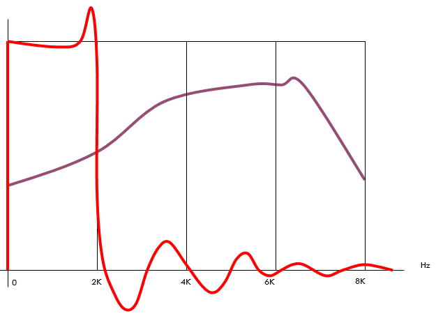
The following diagram shows a possible filterbank approach that can be used for frequency beamforming. The signal is sampled at 16kHz. A uniform filter bank with a low pass filter divides it into 4 equal bandwidth subbands. Each subband can be considered narrow bands and phase shift can be applied a constant for each band.
By introducing the filterbank, we successfully overcome the two issues involving frequency beamforming, frequency dependence and time domain causality.