Motion Adaptive Deinterlacing is an essential part of video processing devices where the input video is an interlaced sequence of fields. The goal of a deinterlacer is to create a sequence of output frames at the same rate as the sequence of input fields. Each input field has only odd or even lines from the frame.
Pixels which are not contained in the current field must be created based on other pixels from the current field and/or pixels from previous field(s). The deinterlaced pixel value is a weighting sum of interpolated value from the current field pixels and replicated or preprocessed pixels from the previous field(s). The values of the weights are based on the estimated motion value for the deinterlaced pixel. This motion value is detected by the motion detector.

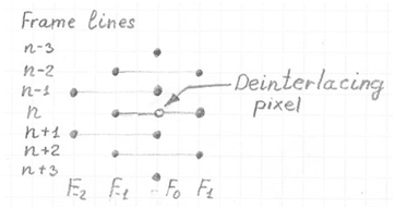
The basic motion detector determines the motion value based on the maximum absolute value of the same location pixel differences from the closest same polarity fields in the deinterlacing pixel neighborhood. Fig.1 shows columns of luma pixels from adjacent lines from the current field F0, previous two fields F-1 and F-2 and the future field F1. Mentioning the future field means that the deinterlacer and motion detector have delay by one field. Fields F0 and F-2 are fields of the one polarity and fields F1 and F-1 are fields of another polarity. n – is the line number.
The motion value is determined as:
Motion = Gl∙MAX(Y0, Y1, Y2, Y3, Y4),
where
Y0 = |F1(n) – F-1(n)|; Y1 = |F1(n-2) – F-1(n-2)|; Y2 = |F1(n+2) – F-1(n+2)|;
Y3 = |F0(n-1) – F-2(n-1)|; Y4 = |F0(n+1) – F-2(n+1)|,
Gl – is a motion coefficient for luma.
It is possible in rare cases that video may have very low luma motion but high chroma motion. To resolve this issue, the motion has to be detected in a similar way for two chroma sequences of the corresponding fields.
Motion = MAX(MotionY, MotionCr, MotionCb);
MotionY = Gl∙MAX(Y0, Y1, Y2, Y3, Y4),
MotionCr= Gc∙MAX(Cr0,Cr1,Cr2,Cr3,Cr4),
MotionCb= Gc∙MAX(Cr0,Cr1,Cr2,Cr3,Cr4),
To improve the estimated motion value for a particular pixel, the vertical high frequency noise level has to be taken into account. High frequency pattern and noise increase the level of motion. Therefore the motion level has to be reduced for vertical high frequency patterns and in the presence of high level of noise.