Fractional Resampling means changing the sampling rate of a signal by a rational factor of LM . This is needed, for instance, when we want to convert between FS1 = 32 kHz and FS2 = 48 kHz. To achieve this, we need to first interpolate by L and then decimate by M all the while avoiding imaging and aliasing respectively. In this scenario, the interpolation and decimation filters can be replaced by one filter H(z) that meets the following ideal requirements:
If this filter is realizable, it will save us from having to store two sets of coefficients. The requirement for ![]() is to remove images from the interpolated spectrum. Similarly, the requirement for
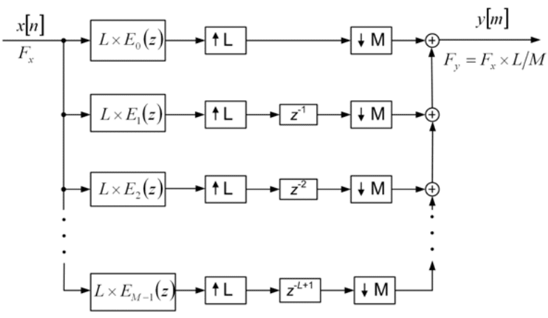
is to remove images from the interpolated spectrum. Similarly, the requirement for ![]() is to prevent spectral aliasing after decimation. The polyphase approach for implementing this filter is shown below:
is to prevent spectral aliasing after decimation. The polyphase approach for implementing this filter is shown below:
Figure 1: Polyphase Fractional Sample Rate Converter [1]
While polyphase approaches are efficient structures in general, this can be made even more efficient by utilizing some noble identities. In other words, we wish to use these identities to make each individual polyphase filter branch more efficient and thereby increase the efficiency of the whole structure. Consider transforming each branch as follows:
Figure 2: Efficient Polyphase Branch [1]
In creating this transformation, we used the relation that when L and M are relatively prime, we can find two integers l0 and m0 such that:
We which we can use to decompose the delay operator z-K as follows:
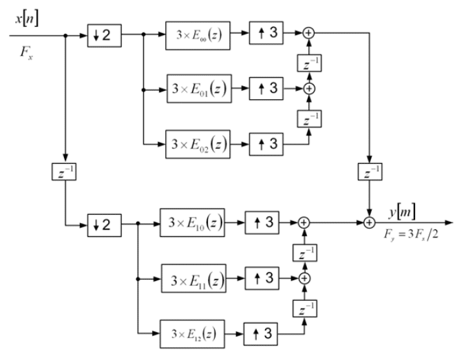
Then using a noble identity pair, we can interchange the upsampling and downsampling operations with the delay operator. Finally, we interchange the delay and filtering operation, and switch the upsampling and downsampling operations due to them being relatively prime. This leads us to the figure above. The filter and downsample operation can be itself implemented as a polyphase filter, leading to a polyphase filter with polyphase branches. In other words, we decompose each polyphase filter component into its own polyphase filter components! For ![]() , the resulting resampling structure is:
, the resulting resampling structure is:
Figure 3: Polyphase Resampler with Polyphase Branches [1]
In this figure, the overall filter H(z) is expressed as:
Each individual filter Ei(z) is then decomposed into:
Notice that here l0 = m0 = 1 due to the L and M being relatively prime. All filtering operations take place at half of the input sample rate, and one third of the output sample rate. Therefore, this shows that in addition to having short filter lengths, this approach reduces the operational sample rate thereby providing even more computational efficiency over the original polyphase structure. It is straightforward to derive the dual structure of the above structure for the sampling rate of ![]() . Due to the stringent restrictions on the originally designed filter H(z), this method is not suitable for fractional rates with large conversion factors such as the conversion from 11.025 kHz to 8 kHz, which requires
. Due to the stringent restrictions on the originally designed filter H(z), this method is not suitable for fractional rates with large conversion factors such as the conversion from 11.025 kHz to 8 kHz, which requires ![]() . For such scenarios, it is best to use an arbitrary sample rate converter, such as the well known Farrow filter.
. For such scenarios, it is best to use an arbitrary sample rate converter, such as the well known Farrow filter.
References
[1] L. Milic. Multirate Filtering For Digital Signal Processing. Hershey, PA: Information Science Reference, 2009


