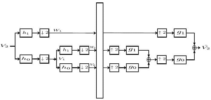
The filterbank method for practical computation of the Continuous Wavelet Transform on a computer is what is known as the Discrete Wavelet Transform (DWT). The filters are arranged in a tree that grows only on one side to eliminate the redundancy inherent in the continuous version of the wavelet transform. The CWT and DWT actually give us the same decomposition when we consider scaling only by a factor of 2, but the DWT is much more practically useful. The filterbank is shown below:
Figure 1: Two Stage Decimated Discrete Wavelet Transform
The filters h0 and h1 are low pass and high pass filters, respectively. As the figure shows, the DWT splits first splits the signal into two half-band signals. One is called the ‘details’ signal occupying the upper half band space W1, and the other is the ‘approximation’ signal occupying the lower half band space V1. Notice that the signal is downsampled by two, denoted by ↓2, after these filters. This is because we want the signal to occupy the whole Nyquist band, so we downsample to decrease the sampling rate. Since the new Nyquist band is half of the original Nyquist band, we downsample by two to decrease the sampling rate by two as well. Therefore, our new Nyquist frequency will be half of the original.
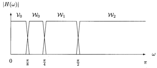
The key in implementing the Discrete Wavelet Transform is that it is recursive algorithm. The lower half band approximation space V1 is again split by our low pass and high pass filters h0 and h1. This forms two new spaces, W0 and V0, that occupy the upper and lower half bands of the original lower half band respectively. Continuing in this manner, we are effectively splitting the spectrum into Octave Bands, as shown below:
Figure 2: Wavelet Octave Bands
Once this is done, we do processing on each subband, denoted by the large rectangular block. Examples of such processing are noise reduction or dereverberation. Finally, we reconstruct the original signal by first upsampling, and passing the sub-signals through the filters g0 and g1 in the order the diagram shows. The result is the enhanced signal which is passed out of the bank.
The question then is, how can we construct these filters h0 and h1? The low pass filter h0 is the ‘father’ wavelet, also known as the scaling function, while the high pass filter h1 is the ‘mother’ wavelet, also known as just the wavelet in the context of the DWT. We have many different ones to pick, from the Daubechies wavelets, to the Symlets, to the Coiets, to the family of Biorthogonal wavelets, to the Myer Wavelet, and the list goes on. For the wavelets defined by Ingrid Daubechies, including the ones she created for others such as the Symlets and the Coiets, the reconstruction filters g0 and g1 are merely time reversed versions of h0 and h1 respectively. For other families of wavelets, such as Biorthogonal wavelets, these reconstruction filters are entirely different than the decomposition ones.

