Interactive Connectivity Establishment (ICE) Protocol is used for NAT transversal. ICE uses a combination of methods including Session Traversal Utility for NAT (STUN) and Traversal Using Relay NAT (TURN). The presence of a Network Address Translator (NAT) presents problems for Voice over IP (VoIP) and WebRTC implementations.
- Communication Software
- Communication Design
- Establishing a WebRTC Media Session
- Voice over IP Technology using SIP
ICE Examples
Consider the example using the Session Initiation Protocol (SIP) where a SIP device with user Bob sits behind a NAT/Firewall and wants to register its location with a SIP registrar located on the public Internet. The SIP device has a non-routable Private IP address 192.168.0.10. The SIP device registers its location with the registrar as sip:bob@192.168.0.10:5060. This tells the registrar that Bob can be reached at the IP address 192.168.0.10 at port 5060 (the default SIP port). This private IP address is meaningless to a device on the public Internet and the registrar would not know how to reach Bob.
A second example involves problems in sending Real-time Transport Protocol (RTP) media. Alice calls Bob and Alice’s invite contains Session Description Protocol (SDP) with her local IP address 10.1.1.10 and media port 1234. Bob accepts Alice’s invite with his SDP containing his local IP address 192.168.0.10 and media port 1234. Both of these IP addresses are meaningless outside the scope of each individual’s private local network and neither party will receive the other’s RTP packets.
Figure 1 shows a typical ICE deployment with two User Agents (UAs) communicating via SIP (or other signaling protocol that performs an offer/answer exchange of SDP messages). ICE use SIP, which means that the NAT traversal of SIP must be provided by another mechanism. ICE allows UAs, who are initially ignorant of their topologies, to discover enough topology information to find communications paths.
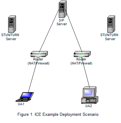
The two UAs are each behind a NAT with unknown properties. They are capable of exchanging SDP messages through an offer/answer exchange used to setup media sessions between the UAs through a SIP server. In addition ICE uses STUN/TURN server(s), each UA can have it’s own or they can use the same one. Both UAs have a list of transport addresses that can be used to communicate with another agent. ICE is used to discover which addresses can connect to each other and the method used to make that connection through the NAT.
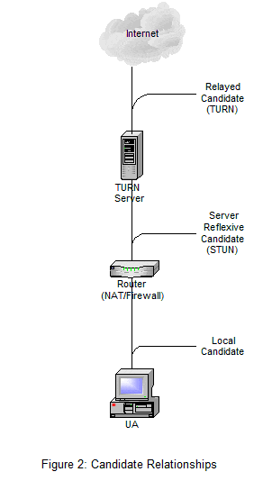
To execute ICE UAs have to identify all address candidates, transport addresses. Transport addresses are a combination of IP address and port for a particular transport protocol. There are three types of candidates:
- Host Candidate – transport address associated with a UA’s local interface
- Relayed Candidate – transport address associated with a TURN server (can only be obtained from a TURN server)
- Server Reflexive Candidate – translated address on the public side of the NAT (obtained from either a STUN server or a TURN server)
Figure 2 shows the relationship of these candidates to the UA.
After UA1 has gathered all of its candidates, it arranges them in order of priority from highest to lowest and sends them to UA2 in attributes in an SDP offer message. UA2 performs the same candidate gathering and sends a SDP response with it’s list of candidates. Each UA takes the two lists of candidates and pairs them up to make candidate pairs. Each UA gathers these into check lists and schedules connectivity checks, STUN request/response transaction, to see which pairs work. Figure 3 shows the components of the candidate pairs that make up the UA check list.

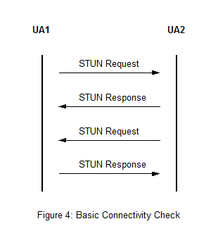
The result of both agents testing is a 4-way handshake on the exact same ports that will be used for media. Figure 4 shows a basic connectivity check.
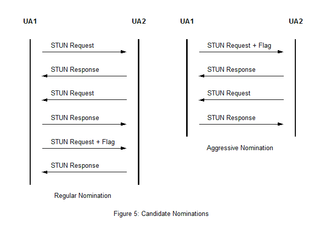
ICE assigns one of the agents as the “Controlling Agent” and the other as the “Controlled Agent”. The controlling agent used the valid candidate pairs to nominate a pair to use for the media. There are two nomination methods that can be used:
- Regular Nomination – The checks continue until there is at least one valid candidate pair. The controlling agent picks from the valid pairs and sends a second STUN request on that pair with a flag to tell the peer that this is the one that is nominated for use.
- Aggressive Nomination – The nomination flag is sent with every STUN request, once the first check succeeds ICE processing for that media stream is finished and a second STUN request is not needed.
Figure 5 shows an example of both nominations.
Each candidate pair in the check list has a state associated with it. The state is assigned by the UA once the check list has been computed. There are five possible states:
- Frozen – This pair can only be checked after being put in the waiting state. To enter the waiting state some other check must succeed first.
- Waiting – As soon as this is the highest priority pair in the check list a check will be performed.
- In-Progress – A check has been sent for this pair and the transaction is in progress
- Succeeded – Successful result from pair check.
- Failed – Failed result from pair check.
Figure 6 shows the state diagram for the candidate pairs.
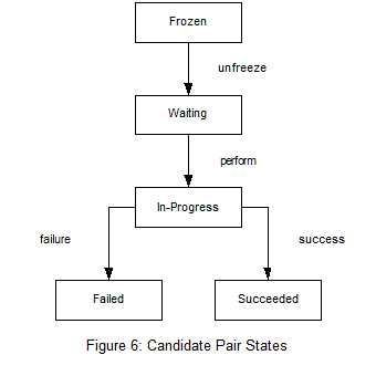
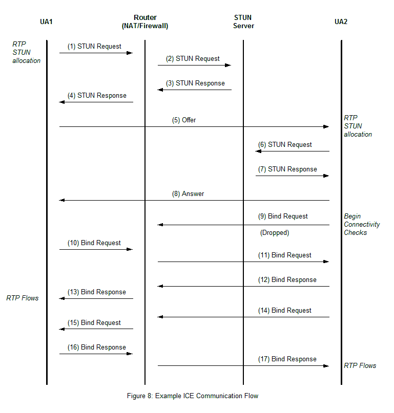
Figure 7 shows a simplified topology that we will use in an example of ICE communication flow. Both UAs are using ICE and aggressive nomination if they are the controller. Both just happen to be using the same STUN server (which is not required but shown in this example for simplicity) which is listening for STUN binding requests. UA1 is behind a NAT that has an endpoint independent mapping property and an address dependent filtering property.
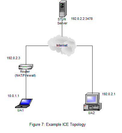
Figure 8 shows the flow of this ICE communication example. After obtaining the host candidate from its local IP address UA1 sends a STUN binding request to get a reflexive candidate (messages 1 to 4). The NAT creates a binding for the request that becomes the server reflexive candidate for RTP. Using the server reflexive candidate UA1 sends an offer message to UA2 (message 5). UA2 proceeds to obtain a server reflexive candidate (messages 6 and 7), which is identical to its host candidate because it is not behind a NAT. The redundant candidate is discarded leaving only the host candidate. Since UA1 started the communication it is deemed as controlling and UA2 is made controlled. UA2 tries a connectivity check but since it is controlled it does not have the proper attributes to reach UA1 through the NAT so the request is dropped (message 9). UA1 being the controlling party has the attribute to traverse the NAT device with its aggressive nomination STUN connectivity check (messages 10 to 13). After receiving the STUN binding request with aggressive nomination UA2 does a matching check using the attribute from UA1’s STUN binding request to verify the connection (messages 14 to 16). At this point both UAs have verified that the connection is valid and it has been nominated for use for this media stream. Both UAs can now send media through this connection.
