In speech processing, we often talk about ratios that describe how the frequency of one tone is related to another. An octave is such a ratio, and represents a doubling in frequency. For example, the first octave above concert A (440 Hz) is 880Hz. The audible range for human creatures extends from about 20Hz to 20kHz. Therefore, the audio spectrum comprises 11 octaves. An octave bank is then a non-uniform filter bank that can bandpass your incoming signals to isolate these octaves. An octave filter bank is traditionally formed by iterative spectrum bisection over the bandwidth of interest.
Octave Filter Bank
To create an octave filter bank, we first need to set a center band from which to iteratively design the bands. Typically, we set the center band to be the 7th octave band of f7ctr = 1kHz. Then the center frequency for the band below is given by fi-1ctr = fi / 2, while the center frequency for the band above is given by fi+1ctr = 2 fictr. For any band i, the bandwidth can then be described as BWfi = 21/2 fi – fi / 21/2. The human hearing mechanism is not that simple however. To better produce our receiver characteristics, we often wish to utilize Third Octave Banks instead. Now we let the 19th band denote our center band, which still has f19ctr = 1kHz. We then define the center frequencies for the band below and band above by fi-1ctr = fi / 21/3 and fi+1ctr = 21/3 fi respectively. For any band i, the bandwidth is then BWfi = 21/6 fi – fi / 21/6.
The Fast Filter Bank

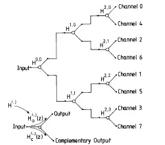
The problem with Octave filter banks is their inherent delay and computational complexity. Traditional asymmetric b-tree construction leads to unbearable delays in real time audio processing, and multi-channel convolution is computationally expensive when using practically good resolution filtering. Using a sliding FFT to reduce the complexity results in a degraded frequency response due to the crude low and high pass filters used. We can merge the selectivity of the octave banks with the speed of the sliding FFT by using the Fast Filter Bank [1], as shown in Figure 1.
Essentially, we are just doing an FFT using coefficients other than the standard Euler basis. In other words, we can these coefficients be coefficients of causal symmetric half-band filters. We let Ha denote the high pass half band filter, and Hc denote the low pass half band filter, where the subscript c serves to emphasize the complementary nature of the operation. We can create each filter Hi,j by modifying the delays z associated with Hi. Specifically, we replace each delay by a delay and multiply. Thus, z becomes ![]() where N = 2L is the number of channels, aka the length of the FFT, and
where N = 2L is the number of channels, aka the length of the FFT, and ![]() and
and ![]() is the bit-reversed version of the frequency shifting integer j. The synthesis part of the bank can be described as a sum across the N channels:
is the bit-reversed version of the frequency shifting integer j. The synthesis part of the bank can be described as a sum across the N channels:
Bounded Q Fast Filter Bank
The Bounded Q Fast Filter Bank implements the Fast Filter Bank but uses specific transfer functions to do so. As [2] explains, the idea is to split the signal into a number of octaves, and split each octave into a number of sub-channels for linear processing. When the signal x[n] is passed through the filter bank, we isolate the high frequency components from the low frequency components using the appropriate filter respectively. For the first run, this will split the spectrum into two halves. From there, we sent each half spectrum, now downsampled versions, output to another round of fast filter banking. The output of this second round will have split the octaves into half octaves. This process is continued until all of the octaves are split apart. The signal can then be recovered by applying the reverse operations after processing. In other words, the Bounded Q Fast Filter Bank is just an iterative filter bank scheme.
Reduced Delay FFB
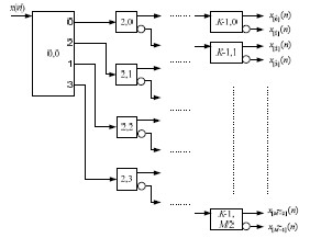
To reduce the delay inherent in this tree structured splitting, [3] proposes the use of a Reduced Delay FFB (RDFFB). In this scheme, the first stage is as a block, which gives us a four channel output. From there, the fast filter bank can proceed as normal. By pre-splitting the signal, we are eliminating the part of the filter bank with the highest complexity. The remaining stages have much more shallowed butterflies to perform. The Reduced Delay FFB is shown in the following figure:

Of course, you don’t have to use 4 channels. If you have 8 channels available then it would behoove you to try to use all 8 such that you could perform a larger FFT and thus get more resolution for the same delay. For use with the BQFFB, each channel could be assigned a different part of the frequency spectrum, and the subsequent splitting could be done much faster.
Using a filter bank will inevitably increase the delay of your system, and improper design can actually harm your frequency resolution relative to a stricly frame based solution. Using the FFB, you can minimize delay while utilizing a decent frequency resolution. The BQFFB takes advantage of the improved spectral resolution of the FFB to break the signal into high resolution octave banks in an iterative manner. These iterations can be reduced by using multiple channels in a RDFFB. The main benefit for using a octave band filters is their mimicry of the human auditory system, thus allowing the resulting algorithm to take advantage of auditory masking effects for improving the results of the speech enhancement scheme in question.
References
[1] Y. Lim, B. Farhang-Boroujeny, “Fast Filter Bank,” IEEE Transactions of Circuits and Systems – II: Analog and Digital Signal Processing. Vol. 39, No. 5, pp. 316-318, May 1992.
[2] F. Diniz et al, “A Bounded-Q Fast Filter Bank for Audio Signal Analysis”, International Symposium on Telecommunications. pp.1015-1019, 2006. – [3] J.W. Lee, Y.C. Lim, “Efficient fast filter bank with a reduced delay”, IEEE Asia Pacific Conference on Circuits and Systems. pp. 1430-1433, 2008.