What Is Microphone Array?
Microphone arrays are one of the most advanced tools in improving speech quality. A single microphone can only provide so much directivity and thus so much reduction in noise and reverberation without a post-processing solution. A microphone array effectively does quality enhancement implicitly by focusing a receiving radiation pattern in the direction of a desired signal, thereby reducing interference and improving the quality of the captured sound.
Microphone Arrays
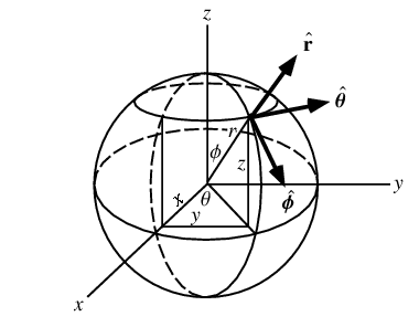
To understand how microphone arrays work, we consider the following figure.
Figure 1: The Spherical Coordinate System [1]
Suppose that a plane wave is incident along a unit vector ρ that starts at the origin. The vector is thought of as a unit vector because we don’t know exactly where the sound source is in space. This vector is given in spherical coordinates by:
To calculate the delay experienced at the ith microphone, we consider its position relative to the origin as ![]() . If the microphone is located at position
. If the microphone is located at position ![]() , then this vector is given by:
, then this vector is given by:
With the speed of sound being c ≈ 333 m/s , the time delay relative to the origin of the wavefront impinging on the ith microphone is given by:
In terms of samples it is given by:
And in terms of frames it is given by:
Where O is the frame hop size. In the frequency domain, this time lag will be experienced as a phase shift. We can express this phase shift as:
Frequently in spatial processing, we would like to incorporate wavenumbers because wavenumbers represent the number of waves in a spatial volume. Therefore, converting this frequency domain phase shift into the wavenumber domain, we get:
Where ![]() is the wavevector, defined as:
is the wavevector, defined as:
Writing things more explicitly, we write Фi(ω, ϴ, ф) and note that this quantity represents the spatio-temporal delay between the ith microphone and the origin microphone. Each microphone will have its own spatio-temporal delay. For a given frequency and incident angle, we place all of these delays into a vector:
Where (•|•)H represents Hermitian transpose. The first element indicates the microphone with zero delay, used a time reference for the other microphones. This vector is called the array response vector, or manifold vector, but most usefully known as the steering vector, and represents how the array will respond to plane waves of frequency ω incident along direction ![]() in 3D space. Calculating this vector continuously for every frequency and every incident angle pair gives you the array manifold D, which is a higher-dimensional receiver space.
in 3D space. Calculating this vector continuously for every frequency and every incident angle pair gives you the array manifold D, which is a higher-dimensional receiver space.
Notice that no array geometry was assumed in the derivation of the steering vector, neither was any microphone directivity pattern, and the derivation was done in 3 dimensions, making it applicable to any geometry. Assuming you know each microphone’s directivity pattern ![]() (ω, ϴ, ф), they can be incorporated into each manifold vector by:
(ω, ϴ, ф), they can be incorporated into each manifold vector by:
Therefore, the vector ![]() gives your specific microphone array’s manifold DA This manifold tells you everything you need to know about how your microphone array will respond to any plane wave of any frequency. The problem with this approach is that the array manifold is difficult to obtain. At best, it can be approximated by sampling the manifold at discrete frequencies and incident angle pairs under careful experimental conditions, as the manifold is a continuous mathematical object and real world microphone characteristics often differ from theory. For speech applications, microphone arrays are usually small with few elements and need to cover only the audible range of the EM spectrum. Therefore, relative to other applications like wireless beamforming, the specific array manifold can often be pre-calculated and stored in memory.
gives your specific microphone array’s manifold DA This manifold tells you everything you need to know about how your microphone array will respond to any plane wave of any frequency. The problem with this approach is that the array manifold is difficult to obtain. At best, it can be approximated by sampling the manifold at discrete frequencies and incident angle pairs under careful experimental conditions, as the manifold is a continuous mathematical object and real world microphone characteristics often differ from theory. For speech applications, microphone arrays are usually small with few elements and need to cover only the audible range of the EM spectrum. Therefore, relative to other applications like wireless beamforming, the specific array manifold can often be pre-calculated and stored in memory.
Unfortunately, any realized steering vector will not be fully accurate for all frequencies and angle pairs, thus causing steering inaccuracies. To make things worse, the individual microphone characteristics will distort the beamshape such that undesirable sidelobes and frequency dependent attenutation will occur. To ensure signals in the look direction are passed with a gain of G, while those outside the look direction are attenuated, thus reducing the real world signal distortion, we use the beamformer response vector defined as:
Where ![]() is a weighting vector, and (•|•)C represents the standard inner product taking values over a complex field. We also often work with the beampattern defined as |Ad|2. We can write this in another perhaps more familiar way:
is a weighting vector, and (•|•)C represents the standard inner product taking values over a complex field. We also often work with the beampattern defined as |Ad|2. We can write this in another perhaps more familiar way:
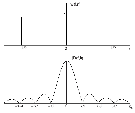
Where m is the microphone index. For a fixed frequency, this is the Discrete Fourier Transform of the weighting vector across the microphones. For a continuous linear array of length L with uniform weighting w(ω,m) = rect(m/L) this is most easily seen, as the beamformer response will then be r = Lsinc(kxL). Notice in the figure below that the nulls occur at regular fractional spacings x = mλ/L.
Figure 2: Linear Array Uniform Weighting [2]
Where kx is the x component of the wavevector. Once we have the directivity calculated for every frequency and every incident angle pair, we can visualize the directivity of our array. We use the phase component of the weight vector to steer the microphones in the desired direction. This changing the look direction to create maximum directivity in the direction of the incident wave is called Beamsteering. The magnitude of the weight vector is to gain the desired signal and attenuate the interference. Using the magnitude in such a way is called Nullsteering. Assuming we want to steer the response to an incident wave at ![]() i (ϴi, фi) we then let the weights be:
i (ϴi, фi) we then let the weights be:
Therefore the directivity pattern is:
So, essentially, there are two steps to choosing the weight vector. First, we estimate where the sound is being sourced from to create the phase vector, and second, we must find the optimal set of magnitudes. Since space and time are inherently linked, these two processes are inexorably linked. In other words, error in the source localization will lead to the computation of suboptimal weights with respect to the reality of the sound source.
Sometimes it is preferable to use the frequency domain instead [3]. In this case, we are interested in what happens in the cross-power-spectrum. Consider that the time delay to the ith microphone is τi. Then the cross-correlation between the reference and the ith microphone’s received signal is:
Where RSS is the true speech signal’s autocorrelation. In the frequency domain, this transforms to:
Where GSS is the autospectrum of the true speech. In other words, the time delay manifests as a phase component of the autospectrum of the signal. Speech signals are non-dispersive signals, which means that the different frequency components all move at the same speed, the phase speed or group velocity of the wave, so that any two microphones will experience a constant phase difference during the time interval in which they receive speech. In contrast, noise signals are modeled as dispersive, such that any two microphones will experience a random phase difference across the interval in which they receive noise. This phase difference can then be used to find the direction of the sound source. Notice that invariably as the SNR decreases, the variability in the phase difference between microphones increases, and thus the source localization accuracy will decrease as well.
Array Factors of Common Geometries
We saw earlier how to add a steering vector to the array response to account for an incident plane wave at any angle in (14). Across the microphone index, this is essentially adding a progressive phase shift, corresponding to the time of arrival delay, on each of the microphone outputs. This progressive shift is often denoted by the addition of a factor βm to the origin response.
Linear Arrays
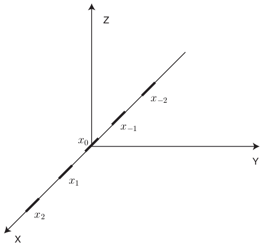
Figure 3: Uniform Linear Array [2]
Consider a linear array as shown in the above figure. In this case, the position vectors are ![]() = [xm, 0, 0]. Hence the phase relation reduces to:
= [xm, 0, 0]. Hence the phase relation reduces to:
Denoting βxm as the required phase shift for a steered response of microphone m, the array response can be written as:
When the microphones are equally spaced, βxm = β∀m since the distance between each microphone is now a uniform d. This allows us to simplify the above equation, and let ψ = kxdcos(ϴ)sin(ф) + β such that we can write:
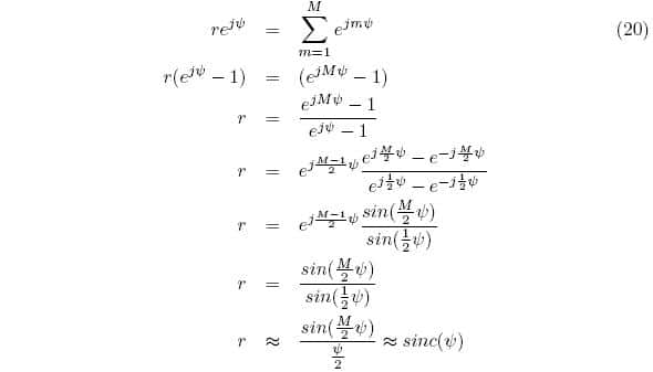
In the special case of uniform weighting, multiply both sides by e jψ and simplify:
Where the last two simplifications assumed a reference microphone at the center of the array, and a small value of ψ respectively. Notice that this is the result shown in figure 2. The beamformer’s directivity for a uniform weighting scheme is a sinc function, which is the fourier dual of the rectangular window. As a side note, cos(ϴ)sin(ф) is often referred to as the directional cosine cos(γ) and gives the angle between the array axis ![]() and the incoming wave
and the incoming wave ![]() centered at the origin.
centered at the origin.
Planar Arrays
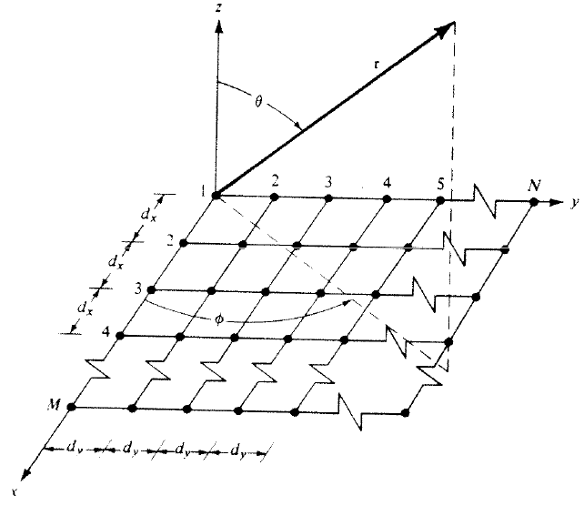
Figure 4: Planar Array [4]
A natural extension to the linear array is the planar array. Assuming there are M microphones along the x axis and N microphones along y, the arrays total response is:
In other words, the array’s response can be found by multiplying the responses for the individual linear arrays in the x and y. To put it simpler, if we let Sxm and Sym be the responses for the individual arrays respectively, then:
Following the above simplification procedure for linear arrays, the resulting array factor for the special case of an uniformly spaced uniformly weighted array is:
Where x = kxdxcos(ϴ)sin(ф)+βx and y = kydysin(ϴ)sin(ф)+βy respectively.
Circular Arrays
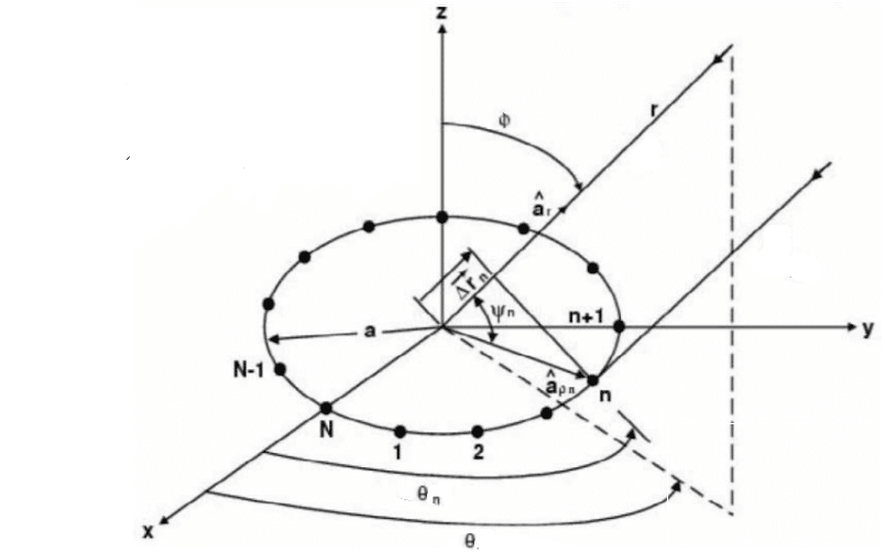
Figure 5: Circular Array [5]
Circular arrays are another extension of the linear array. Like planar arrays, circular arrays can steer between ϴ ϵ [0, 2π]. The figure above shows a plane wave incident on the array. The projection of ![]() onto ρ placed at the center of the array results in an extra distance Δρ that needs to be traversed. The radial position of the mth microphone is given by:
onto ρ placed at the center of the array results in an extra distance Δρ that needs to be traversed. The radial position of the mth microphone is given by:
Then the projection of the radial component ![]() onto
onto ![]() , where
, where ![]() denotes the direction of the incoming plane wave normally denoted by
denotes the direction of the incoming plane wave normally denoted by ![]() and described by
and described by ![]() is:
is:
Where a denotes the radius of the array. The approximation is made for uniformly spaced arrays since we can think of a circle as the one-point compactification of a line. The resulting array factor is then:
In the special case of uniform weighting and uniform spacing this reduces to:
Letting ψβm = |![]() | acos-1 (sin(ϴ)cos(ϴm – ϴ)), the additive steering factor is then ψβm, and we then can write:
| acos-1 (sin(ϴ)cos(ϴm – ϴ)), the additive steering factor is then ψβm, and we then can write:
Microphone Directivity
The previous analysis of the common geometries will only be realized in practice when you are using all perfectly omnidirectional microphones. This is because the individual microphone responses αm (ω, ϴ, ϕ) = 1 in ![]() . Sometimes we wish to use directive microphones to get a different response out of the array.
. Sometimes we wish to use directive microphones to get a different response out of the array.
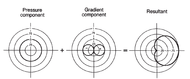
The most common directive microphones are the first order directional microphones. The polar response of these microphones is simply a linear combination of the polar responses of pressure and gradient microphone designs [6]:
Where A is the pressure weighting, B is the gradient weighting, and A+B = 1. The polar pattern is derived by simply adding these two elements around the bearing angle of the microphone as shown below:
Figure 6: General First Order Microphone Pattern [6]
Cardioid Microphone
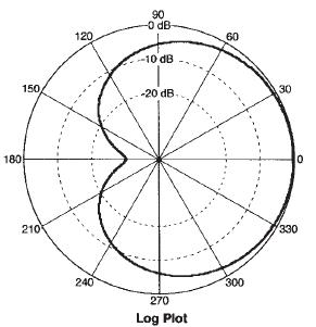
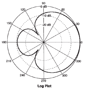
The cardioid microphone is the most common directional microphone in use today. Its directivity results from an equal weighting of pressure and gradient. In other words, the polar response for a cardioid microphone is given by:
The resulting pattern has an attenuation of about -6dB at ±π/2 and is practically zero at π. The cardioid microphone polar directivity plot looks like:
Figure 7: Cardioid Microphone Directivity Pattern [6]
Supercardioid Microphone
The supercardioid microphone pattern is a result of unequal weighting of the pressure and gradient terms. It results in the maximum ratio between the front facing beam and the total beam area. The polar response is given by:
The supercardioid has an attenuation of -12dB at ±π/2 and -11.7dB at π.
The supercardioid microphone polar directivity plot looks like:
Figure 8: Supercardioid Microphone Directivity Pattern [6]
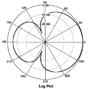
Hypercardioid Microphone
The hypercardioid pattern is another unequal weighting scheme. It results in the highest directivity and distance factor of all the common first order microphones. Its polar response is:
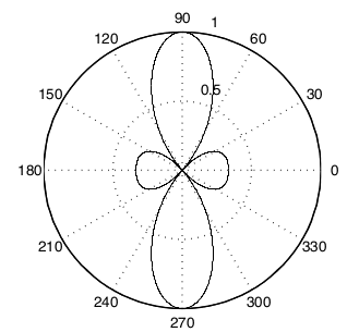
The hypercardioid has an attenuation of -12dB at ±π/2 and -6dB at π. The hypercardioid pattern looks like:
Figure 9: Hypercardioid Microphone Directivity Pattern [6]
In practice, the measured patterns often deviate from theory due to manufacturing tolerances. It is these non-ideal responses that are multiplicatively coupled to the array factors, causing your microphone array to behave slightly differently than the theory predicts. It should be noted that the three dimensional versions can be obtained by rotating the two dimensional pattern around the axis of directivity.
Fundamentals of Spatial Aliasing
Spatial aliasing causes obscurity in the location of sound sources [6]. Basically, spatial aliasing occurs when multiple sources corresponding to different locations produce the same array response vector ![]() . This phenomena is particularly problematic in broadband beamforming as we can often have
. This phenomena is particularly problematic in broadband beamforming as we can often have ![]() (ω1, ϴ1, ф1)=
(ω1, ϴ1, ф1)= ![]() (ω2, ϴ2, ф2). The theory of spatial sampling is equivalent to the theory of temporal sampling and states that a spatial signal must be sampled at:
(ω2, ϴ2, ф2). The theory of spatial sampling is equivalent to the theory of temporal sampling and states that a spatial signal must be sampled at:
Where fρmax is the maximum spatial frequency you want to be able to accurately represent. Across our standard three dimensions, the spatial sampling frequency vector is:
Since ![]() is a unit vector, the maximum spatial frequency you can represent is then:
is a unit vector, the maximum spatial frequency you can represent is then:
Where λmin is the minimum wavelength. Thus, the interelement spacing for each dimension should be:
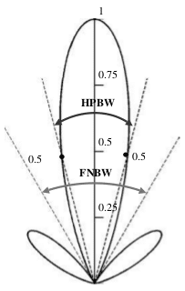
This relation also has a fourier equivalent. The beamwidth of the directivity pattern is defined as the angular separation between two points on opposite sides of the main lobe maximum. The First Null Beam Width (FNBW) determines the extent of the computed pattern’s ability to resolve two adjacent sources seperated by some angular distance [5]. The minimum angular distance between two sources with respect to the microphone array is then:
The Half Power Beam Width (HPBW) is defined as twice the first null beamwidth, and is often the parameter most commonly referred to as just beamwidth.
Figure 10: Beamwidths [5]
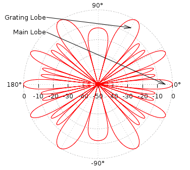
Spatial undersampling results in the presence of grating lobes in the directivity pattern. Grating lobes are basically beams that point away from the look direction. Improper selection of the individual microphones may make the problem worse. These sidelobes lower the SNR of the beamformer by capturing unwanted noise, acoustic echoes, and reverberance. Therefore, high frequencies tend to be more affected by distortion than low frequencies. An example of a particularly bad case of grating lobes for a steered beam is shown in the below:
Figure 11: Grating Lobes [8]
For a linear array, we can fix the azimuth angle to ф = π/2 such that the array look direction is constrained to be in a plane. Frequently, the directivity plots for linear arrays disregard ф all together and give what is known as a polar plot of the directivity as a function of ϴ only.
Figure 12: Linear Array Polar Pattern [2]
As the figure shows, the directivity is high in the look direction of zero degrees, and low on the sides illustrating a good beam pattern for a linear array. The problem shown here is that a linear array can only distinguish signals in the range of ϴ ϵ [0, π]. In other words, sources in the front of the array cannot be distinguished from sources behind the array from the point of view of the array itself. This is often called the front-rear problem for linear arrays. Other array geometries like the planar and circular array can steer ϴ ϵ [0, 2π] so that the front rear-problem is eliminated.
The discussion shows how microphone arrays work. By carefully choosing the complex weights, large increases in directive gain and interference cancellation can be achieved. Different microphone array geometries are suited for different tasks, and it is the requirements of your system that will tell you which design to use.
References
[1] E. W. Weisstein, “Spherical Coordinates.” From MathWorld{A Wolfram Web Resource. http://mathworld.wolfram.com/SphericalCoordinates.html
[2] I.A. McCowan. Robust Speech Recognition using Microphone Arrays, PhD Thesis, Queensland Uni- versity of Technology, Australia, 2001
[3] A. Piersol, “Time Delay estimation using phase data”, IEEE Transactions on Acoustics, Speech and Signal Processing, vol. 29, no. 3, Jun 1981
[4] W. L. Stutzman, C. Thiele, Antenna Theory and Design. 1st ed. Hoboken, NJ: John Wiley & Sons, Inc., 1981
[5] C. Balanis, Antenna Theory: Analysis and Design. 3rd ed. Hoboken, NJ: John Wiley & Sons, Inc., 2005
[6] V. Madisetti, D. B. Williams, The Digital Signal Processing Handbook. 1st ed. Salem, MA: CRC Press LLC., 1998
[7] J. Eargle, The Microphone Book. 2nd ed. Burlington, MA: Elsevier., 2005
[8] A. Greenstead. (2012, October 10). Delay Sum Beamforming – The Lab Book Pages [Online]. Available: http://www.labbookpages.co.uk/audio/beamforming/delaySum.html
