After the high-level functionality of a microphone array has been verified, the next step is to verify the performance of the beamformer. The design goal of any wideband acoustic beamforming solution is to provide unity gain in the desired beam direction. This should be true for the entire bandwidth of the signal. The beamforming frequency response needs to be tested and verified. Testing of the beamformer needs to be performed in anechoic chamber and the sound source should be placed in position to minimize scattering effects.
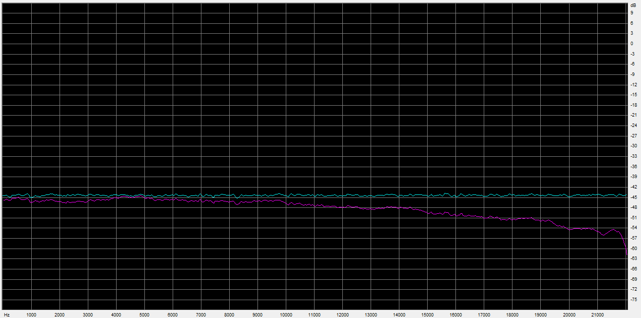
The product design parameters needed for creating the beamforming weights are: the number of microphones, the position of the microphones, and the sampling rate of the audio. The number and position of the microphones have been decided on early in a product design, but the sampling rate can easily be changed after the hardware design is complete. A mismatch between the beamforming design and the actual product firmware will result in a non-unity frequency response of the beamformer during testing. The image below shows frequency response of beamformer (magenta), and that of an input signal (cyan).
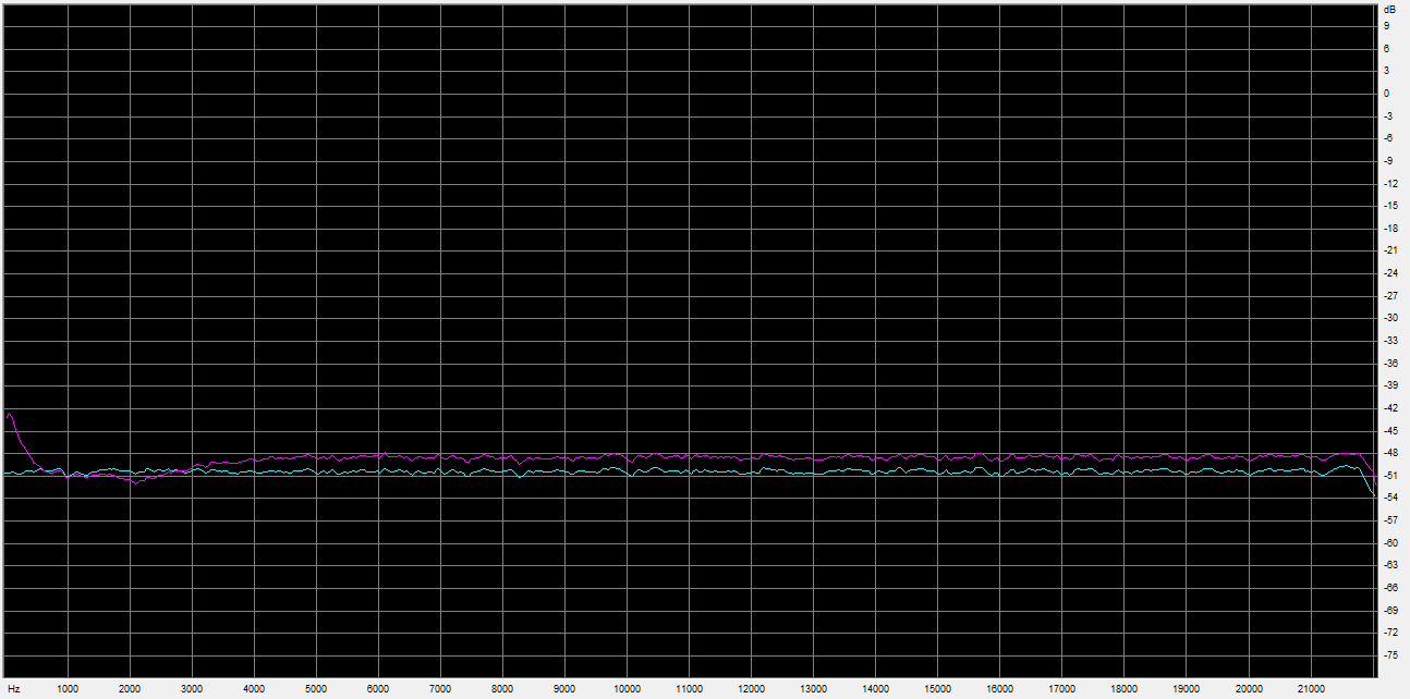
Another common issue is the magnitude mismatch between microphones. Manufacturing variability of the microphones, ADCs, and preamplifiers can create a mismatch in magnitude at the microphones. Without proper calibration, as described in Microphone Array Magnitude Calibration for Beamforming, the frequency response of the beamformer will not be uniform, as shown in the image below (beamformer – magenta, input – cyan).
If testing of the beamformer reveal these type of beamforming frequency responses, then verify your beamforming configuration parameters, and review the signal levels of each of the microphones.