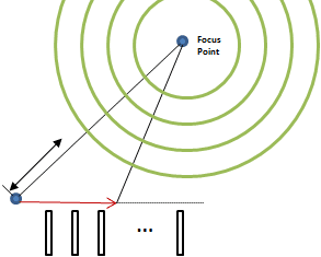
A Beamformer is a system for acoustic echo cancellation (AEC) and noise reduction (ANR) that combines the input from multiple microphones such that signals coming from a preferred direction are added constructively, while those coming from other directions are combined diffusively or destructively.
The spatial arrangement of these microphones can vary widely according to the specific application, but for mathematical simplicity a linear array of equally spaced microphones is often assumed.
Assuming each microphone output →ym is attached to its own FIR filter →gm the output of the beamformer is given by [1]:
Where M is the number of microphones and (•│•) denotes the standard inner product in RN. At discrete time index n the FIR filter can be represented as:
And →y[n] represents the last N microphone samples starting from index n. Assuming a far field source, a plane wave with spectrum S(ejΩ) arrives along the direction →r relative to the microphone of interest. Each microphone’s spectra is then given by:
Where Hm(ejΩ, →r) is the spatial frequency response of the mth microphone’s receiving characteristic, and τm is the time it takes for the wave to reach the mth microphone. This delay is given by:
Where fs is the sampling frequency, c is the speed of sound, and →rm is the position vector of the mth microphone relative to the center of the array. This leads us to the spectrum of the beamformer output:
Beamformer Design
As the previous equation shows, the beamformer’s output is a function of both the construction of the microphone itself, as well as the impulse response of its associated FIR filter. In speech processing, omnidirectional or cardioids microphones are often used. Omnidirectional microphones have a receiving characteristic of:
Whereas cardioid microphones have a receiving characteristic of:
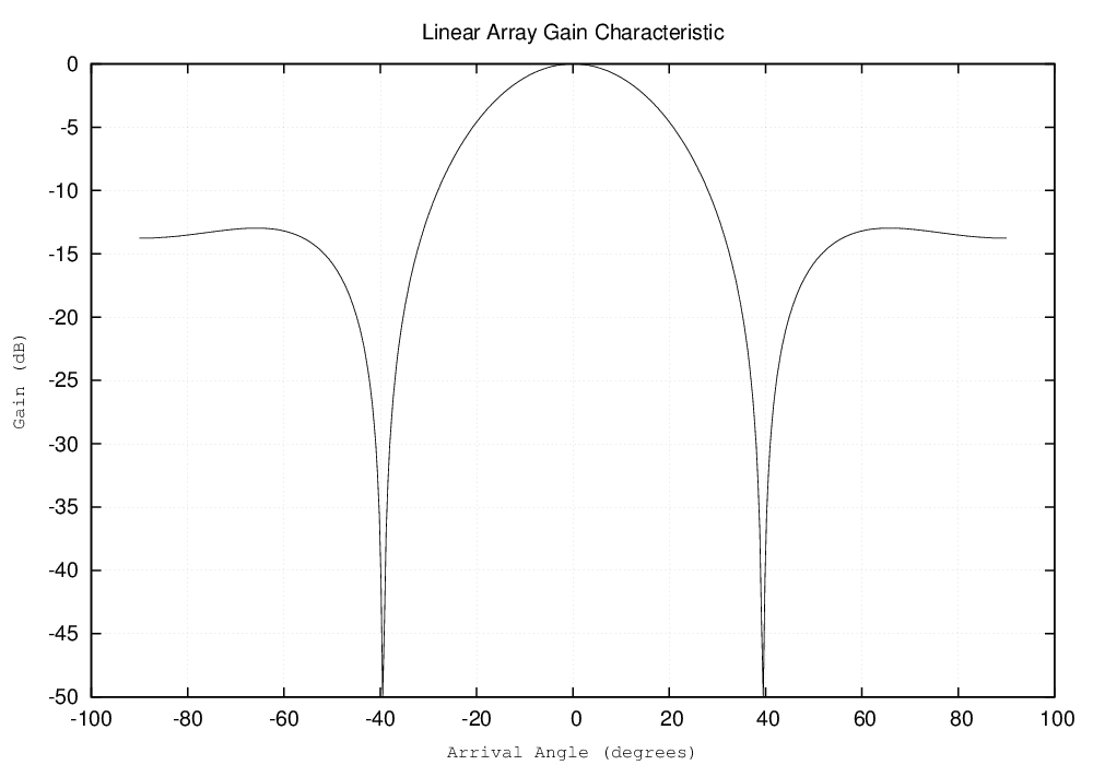
Assuming a linear array of equally spaced omnidirectional microphones, one can see that the spacing, number of microphones, and frequencies of interest will all contribute to the performance of the beamformer. A typical application may be to pick up a male speaker’s voice, whose fundamental is taken to be f = 135 Hz. For small microphone arrays ( m < 50 ), an optimal spacing is 4 cm due to c ≈ 343 m/s. This gives us the smooth single peak gain characteristic shown below:
Figure 1: 10 Microphone Array with 4 cm Spacing at 135 Hz
If we change the spacing to 40 cm, we see significant sidelobes starting to appear. This means our system will start boosting signals that are outside our spatial range of interest. The figure below illustrates this effect:
Figure 2: 10 Microphone Array with 40 cm Spacing at 135 Hz
This effect can be mimicked with a spacing of 4cm by increasing the number of microphones. These sidelobes are also called grating lobes, and are a result of the extra distance to the farthest microphones being close to multiples of the signal wavelength. In this case, the beamformer essentially receives an extra copy of the signal at the center of the array, thereby correlating the outputs of the microphones. From this point, it is clear how changing the frequencies of interest will similarly effect the performance of the array. What is not so intuitive is how more complicated geometries may impact the performance of your beamformer.
Generalized Sidelobe Canceller
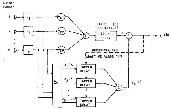
Luckily, the formulation given in the first section gives the designer some flexibility when constrained to a given piece of hardware. By adjusting the weights of the FIR filters, the spatial selectivity problem can be mitigated. The most basic solution would be to introduce delays at the output of the microphone such that signals outside our spatial range of interest will be added destructively or at least diffusively. Such a solution belongs to a general class of solutions called Filter-and-Sum (FAS) Beamforming. One of the most widely used FAS techniques is the Generalized Sidelobe Canceller (GSC) [2] shown below:
Figure 3: The Generalized Sidelobe Canceller [2]
The idea behind the GSC is to subtract the interfering signals from the output of the beamformer by blocking the desired signal in the bottom subtractive half. The top half contains fixed delay FIR filters. Since the interfering signal will be present in both the top and bottom halves of the GSC, ideally only the desired signal will be passed as an output. This blocking is done by the blocking matrix WS. Denoting →x as the microphone signal this time, this matrix gives us an output:
In order to assure the signal is blocked, the rows of the blocking matrix must be linearly independent and:
Where →wm denotes a row of the blocking matrix. After the blocking matrix, the signal is fed into an adaptive FIR filter →gW,m, summed, and the output yA is produced:
The output of the beamformer is then:
Where yc denotes the output from the ‘conventional’ fixed delay beamformer on the top path. The filter coefficients can be updated with NLMS as shown below:
Beamforming Applications
For a highly dynamic speech environment, the most obvious modification to GSC is to make the blocking matrix adaptive, which will allow the beamformer to be steered according to how the signal of interest is moving. While this gives us a very general algorithm, for other applications such as car interior acoustics, the positions of the sources will be fixed and thus this modification might introduce unnecessary computational overhead.
Beamforming can be applied to Blind Signal Separation to greatly improve the Signal to Noise Ratios. Similarly, Acoustic Echo Cancellers can benefit from having a Beamformer on the front end, while Beamformers can benefit from having Acoustic Echo Cancellers on their front ends.
Beamforming is becoming increasingly important as a mechanism for the incorporation of 3D sound into holography and as a safer alternative for use in medical scanning technologies.
More Information
References
[1] E. Hansler, G. Schmidt, “Beamforming,” in Acoustic Echo and Noise Control A Practical Approach. 1st ed. Hoboken, NJ: John Wiley & Sons, Inc., 2004, ch. 11, pp. 267 – 295.
[2] L. Griffiths, C. Jim, “An Alternative Approach to Linearly Constrained Adaptive Beamforming”, IEEE Transactions on Antennas and Propagation, vol. 30, no. 1, Jan 1982.


