Cellular phone connectivity to a cellular network is realized via the transmitting channel (uplink) and receiving channel (downlink) and there is no coupling between these two channels at the near end, except for the acoustical coupling (cf. Ref. [1, 2]). There are two main kinds of acoustical coupling in the cellular phone: short coupling and long coupling.

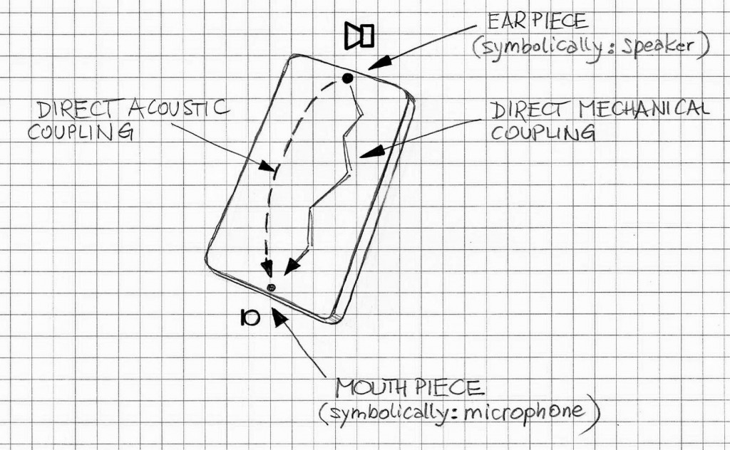
Short coupling: Cellular phones equipped with ear-piece (miniature loudspeaker) and mouth-piece (miniature microphone) manifest the coupling between these two transducers via acoustic path (due to acoustic leak between enclosure of the earpiece and the ear flap, or pinna, cf. Ref. [3]) as well as via mechanical path (through the common physical elements of the cellular phone enclosure and well other elements, due to their physical layout and mounting in the phone set enclosure).
Figure 1 illustrates the “short” acoustic coupling contributing to the echo path. Two components of the echo path are emphasized: the direct coupling via acoustic path and the direct coupling via mechanical path. Depending on the individual construction and structure of the given cellular telephone set, and also depending on the actual individual style of using the cell phone set by the user, either of these two paths may be dominant. The common feature of these paths is that although they both contribute to the overall echo path, the resultant echo path is relatively short and seldom exceeds 0.5 ms of the direct echo path delay; it may exceed 0.5ms only if the acoustic sealing is poor, for whatever reason (and then a tangible portion of acoustic energy is emitted to the acoustic field), and if in the vicinity of the cellular phone there are reflecting elements.

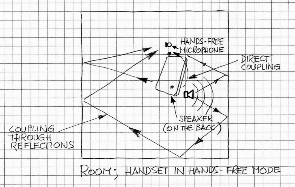
Long coupling: Cellular telephone sets are equipped with the miniature speaker for the hands-free mode. Depending on the make and model of the phone, there may be also an additional dedicated microphone, or a couple of microphones, to support the hands-free mode. Due to the nature of the use cases involving hands-free operation, in addition to the direct acoustical coupling combined with mechanical coupling, as discussed in the paragraph on “short” coupling, there is a room effect that contributes very significantly to the echo path as observed between the receiving audio channel of the downlink and transmitting audio channel of the uplink.
Figure 2 depicts the “long” acoustic coupling contributing to the echo path. The contribution of the room effect to the overall echo path includes early reflections of the acoustic signal from the different objects in the room as well as late reflections (and, typically, there are very many of these), which constitute, as a whole, the reverberation effect. Depending on the room acoustic conditions and room size, as well as depending of the specific position and orientation of the handset in the room, the echo path may be very dependent on these factors. The “long” coupling makes the echo path delay (a.k.a. echo path span) significantly longer than in the case of the “short” coupling. It is not uncommon to see the echo path impulse response longer than 400ms, as observed and measured using the telephone’s hands-free speaker and the telephone’s microphone (cf. Ref. [4, 5]).
There are additional characteristics of the “short” coupling and “long” coupling that differentiate these too. “Short” coupling affects the echo path mostly in the static way. In other words, the echo path’s impulse response does not vary a lot (except for specific and not particularly common reasons, such as changing the style of holding the phone during the same telephone call or other similar reasons contributing to variations of the echo path). In contrast, the “long” echo path’s impulse response may be changing significantly in a continuous fashion during the telephone call. These changes are typically caused by changes of the acoustic scene in the room as well as by changes of the position and/or orientation of the telephone handset.
In both cases, i.e., in “short” coupling and “long” coupling, the energy of the echo path impulse response (and thus ERL) depends on the volume settings on the telephone set. These settings, particularly in the case of hands-free mode (i.e., when the “long” coupling is under consideration), influence the degree of non-linearity of the echo path, as observed and measured at the terminals of the loudspeaker and the microphone. Thus, strictly speaking, the acoustic echo paths, as described in this note, are “non-linear”. Consequently, in order to describe them mathematically and with all details, non-linear system functions (such as a transfer function) should be used. However, in most practical cases, the modeling is done using linear transfer functions.
VOCAL’s acoustic echo cancellers are part of our solution for secure, real-time communications of voice, video and data over mobile, radio or other IP networks. Contact us to discuss your mobile application with our engineering staff.
More Information
References
- Universal Mobile Telecommunications System (UMTS); User Equipment (UE) radio transmission and reception (FDD) (3GPP TS 25.101 version 6.19.0 Release 6) ETSI TS 125 101 V6.19.0 (2009-03).
- Fundamentals of Voice-Quality Engineering in Wireless Networks, Avi Perry; Cambridge University Press; 2007
- Comparative acoustical impedance- and application force measurements on the present ITU-T Type 3.3 pinna simulator and a softer Type 3.3 like pinna simulator and on real ears. ITU-T STUDY GROUP 12 – DELAYED CONTRIBUTION 121, Geneva, 17-21 October 2005.
- Acoustic Echo Path Characteristics and AEC
- Acoustic Echo Canceller