In 5G wireless communications, a very large number of antennas are employed at the base station, which provide enough degrees-of-freedom (DOFs) to suppress interference. Considering the moving characteristics of users in wireless communication network, it is necessary to adaptively calculate the beamforming weight based on the array received data. Among various adaptive beamformers, the minimum variance distortionless response (MVDR) beamformer, also known as the Capon beamformer, is the most popular one, which is a function of interference-plus-noise covariance matrix and desired signal steering vector.
In practical applications, however, the interference-plus-noise covariance matrix is not available. It is usually replaced by the sample covariance matrix or its diagonal loaded version, which leads to a minimum power distortionless response (MPDR) beamformer. Unfortunately, the MPDR beamformer unavoidably causes the signal self-nulling phenomenon, especially when the signal-to-noise ratio (SNR) is high. As such, the theoretical array gain is hard to touch. Here, the array gain of an optimal beamformer equals to the number of antennas. For example, the theoretic array gain is 10 dB for a ten antennas array, and 20 dB for a one-hundred antennas array.
In order to avoid or mitigate the signal-nulling phenomenon, a signal-free interference-plus-noise covariance matrix is required for adaptive beamformer design. Assuming the desired signal is distinguishable from the interferers in the spatial domain, the interference-plus-noise covariance matrix for a given desired user can be reconstructed as
 \boldsymbol{d}(\theta) \boldsymbol{d}^{\mathrm{G}}(\theta) d\theta, \nonumber")
where ") is the steering vector associated with a hypothetical direction
is the steering vector associated with a hypothetical direction  ,
,  = \frac{1}{\boldsymbol{d}^{\mathrm{H}}(\theta) \hat{\boldsymbol{R}}^{-1} \boldsymbol{d}(\theta)}") is the Capon spatial spectrum estimator with the sample covariance matrix
is the Capon spatial spectrum estimator with the sample covariance matrix  \boldsymbol{x}^H(k)") averaging over
averaging over  samples,
  is the complement sector of
  . Here, is an angular section in which the desired signal is located. As such, the desired user’s signal does not impinge to the out-of-sector , and
  collects all information on interference and noise in the out-of-sector . Consequently, the desired signal component is excluded from the reconstructed covariance matrix .
Substituting the reconstructed interference-plus-noise covariance matrix into the MVDR beamformer, the interference covariance reconstruction-based MVDR beamformer is given by

is obtained, where  is the presumed steering vector with the signal direction
  .
.
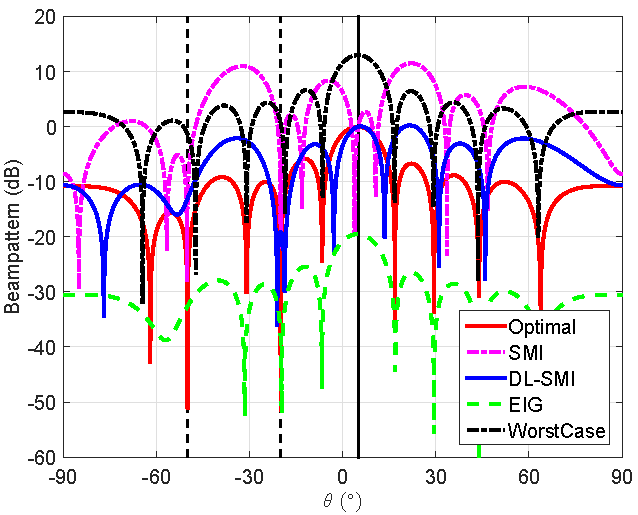
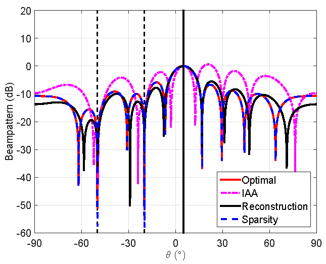
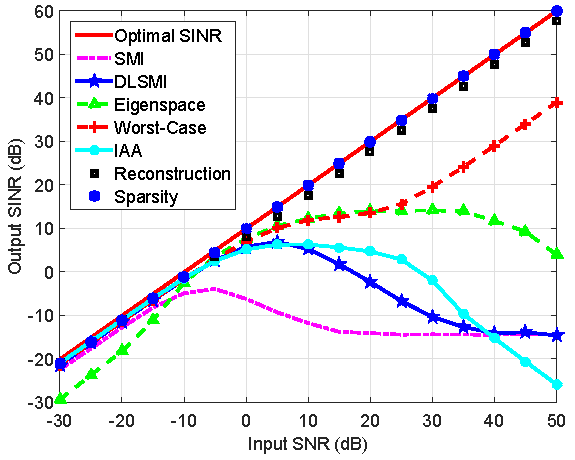
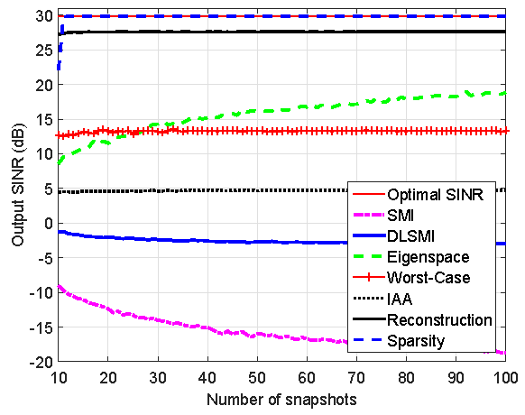
Simulation
For the sake of demonstration, a uniform linear array with  omni-directional sensors spaced half wavelength apart is considered. It is assumed that there is one desired signal from the presumed direction
  and two uncorrelated interferers from
  and
and  , respectively.